8. Planning
8.1. Plan Background
A typical plans popup is shown in Image 8.1.

Image 8.1 Plans popup
The Plans popup is divided into two sections: the top section contains the Quick Planner, and the bottom section contains a list of previously created plans. Please note: if a plan is currently active, pressing the Plans button will display a summary of the plan as shown in Image 8.3
The Quick Plan section is used to make a plan by typing in codes or names of waypoints, coordinates, or bearings & ranges. That is described more in the Quick Planner section below.
The basis for flight planning calculations is shown in Image 8.2. The method of calculation of times and fuel consumed are illustrated. The figures primarily come from the values you have entered for the aircraft you are using in the plan. Fuel and time are calculated on a per leg basis. At the initial takeoff point you can set the fuel available on takeoff, and at each landing point you can select whether to add fuel or not.
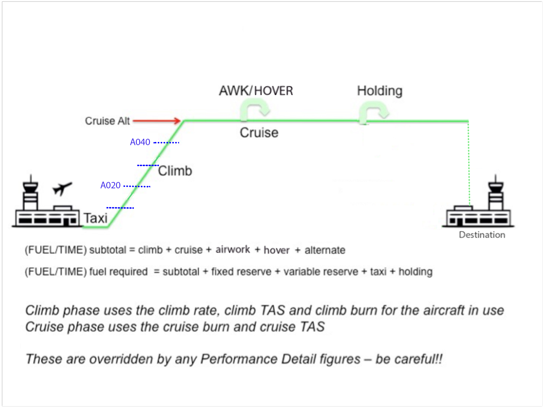
Image 8.2 Planner calculation method
When using basic performance figures the calculations are straightforward. The fuel/time is calculated every 1000’ by interpolation for climb, followed (if applicable) by a cruise segment. Descents are not calculated, instead a cruise leg is used. This produces more conservative results, albeit only marginally different for light aircraft. Anecdotally, the author has found that simple straightforward performance numbers yield quite accurate results for small aircraft (i.e. Cirrus SR22, Robinson R44). Image 8.2 shows a typical flight plan, with calculations for Time, Fuel, and Distance, made every 1000’ for the climb. Then the remainder of the leg is calculated at Cruise Fuel Burn and TAS to the destination; no descent is calculated.
Alternate legs are calculated using a climb leg from the destination elevation to a nominated altitude, plus the remainder of the segment at cruise. Alternate fuel calculations do not include a variable reserve.
8.2. Initiating a plan
To start a plan you need a starting point. You can do this three ways on the Map page, namely:
Enter a Quick Plan (described in next section)
Tap near the starting point on the map, select the location in the resulting Closest Points popup, and then select ‘Set waypoint As Origin of Plan’ (covered below in Map Planning)
Tap the ‘Search’ button on the map page, search for the waypoint textually, select it and then select ‘Set waypoint As Origin of Plan’
A brief demonstration video on how to initiate a plan is available on our YouTube channel.
8.3. Quick Planner
The Quick Planner is perhaps the easiest way of entering a plan. To use the Quick Planner, first tap on the Plans button, then tap in the Quick Plan field and start typing a waypoint. The Quick Planner will show suggestions as you type. For example start typing ‘Adelaide’ and you will see YPAD at the top of the suggestion list. Use the toggle in the top left corner to switch between VFR or IFR. When IFR is selected the Quick planner will suggest IFR waypoints, and any applicable air routes. At any time press space to insert the top suggestion into the plan. Continue on until you have filled in all the waypoints you desire then press ‘Go’. If only one point is entered into the Quick Planner the ‘Go’ button is replaced with ‘DCT’. Pressing ‘DCT’ creates a Direct To plan from your current location, to the waypoint entered in the Quick Planner.
As well as names and codes the Quick Planner will accept coordinates in various formats, and also radial/distance type waypoints. e.g.
S3448E13837 (S34º 48’, E138º 37’)
YPAD04015 (040ºM 15NM from YPAD)
The Quick Planner functionality is demonstrated in the following video: https://www.youtube.com/watch?v=pPb1rHAgX6M
After pressing ‘Go’ (or ‘DCT’) the Plan Details screen is displayed. The Plan Details screen is described in the next section. To get back to the Plans List / Quick Planner screen, tap the top left button ‘Plans’. Tap on a waypoint to reveal options for ‘Direct To’ and ‘Activate Leg’. Alternatively, tap and hold a waypoint to activate that leg. Previous legs can be activated as necessary.
The GPS HUD on the map page will give you information to navigate to the active waypoint (the active waypoint is always shown in the bottom right GPS HUD box). For more information see the GPS HUD chapter.
8.4. Plan Details
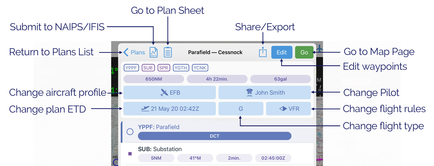
Image 8.3 Plan Details
The Plan Detail screen has the following entries:
- Back to Plans List / Quick Planner
Tap this button to return to the Quick Planner / Plans List.
- NAIPS/IFIS
This button opens the NAIPS flight notification (AU) or IFIS flight plan (NZ) submission form.
- Plan Sheet
This button opens the Plan Sheet (navigation log). For more information see the Plan Sheet section below.
- Share / More Options
Duplicate: creates an exact copy of the plan. The new plan will have the same name with the word ‘copy’ appended.
New Inverted: creates a new plan with all the same waypoints in reverse order. Commonly used when you reach your destination, and want to fly back along the same route! The original plan is saved and can be accessed back in the Plans List.
Share: Used to share a plan with other OzRunways users. Tap to reveal options e.g. AirDrop, Mail etc.
Export: exports the plan in the given format.
Copy route to Clipboard: once the route is copied to the clipboard, you can paste the text into another app e.g. into an email. The original plan is saved and can be accessed back in the Plans List.
PDF Pack: generates a PDF document containing the user-selected items (plan sheet, weather, NOTAMs)
Copy to Quick Plan: pressing this will return you to the Quick Planner / Plans List screen with all the waypoints from the plan pre-filled into the Quick Plan section. Useful if you want to edit your plan using the Quick Planner.
- Edit
After tapping the edit button you can do two things: change the plan name, or delete multiple waypoints. To delete waypoints in edit mode, tap on them and a checkmark will appear on the left hand side. Select all the waypoints you wish to delete and then press the red trash icon in the top bar. When you have finished editing press ‘Done’.
- Go
Pressing Go dismisses the Plan Detail screen and returns you to the map page ready to fly the plan!
- Route overview and details
Below the title bar you will see the overview of your route, the total distance, the total time, and the total expected fuel burn (flight fuel only, excluding reserves). The calculations are based on which aircraft profile is selected for the plan (see below).
- Aircraft
Select the aircraft profile to use in this plan.
- Pilot
Select the pilot profile to use in this plan.
- Departure Date / ETD
Set the ETD for the plan. If you are submitting a plan to NAIPS or IFIS, this ETD will automatically be filled into the plan.
- Flight Type
Select the flight type (General Aviation, Scheduled, Non-scheduled, Military or Other)
- Flight Rules
Select the flight rules (VFR or IFR). This is sticky in that once you set it, the next plan you create will be of the same type.
- Route
All the waypoints in your route are shown in this list. If you have a waypoint set as a landing point this will be indicated by the Landing symbol. Tap on a waypoint to reveal more options: Activate Leg, Direct To, and View. Alternatively, long press on a waypoint to activate it. Below each waypoint are some calculations: distance from preceding waypoint, track from preceding waypoint, and ETA. These calculations are based on which aircraft profile you have selected, and the set ETD. When flying the calculations to the next waypoint are dynamic e.g. distance and time will count down as you get closer.
8.5. Plans List
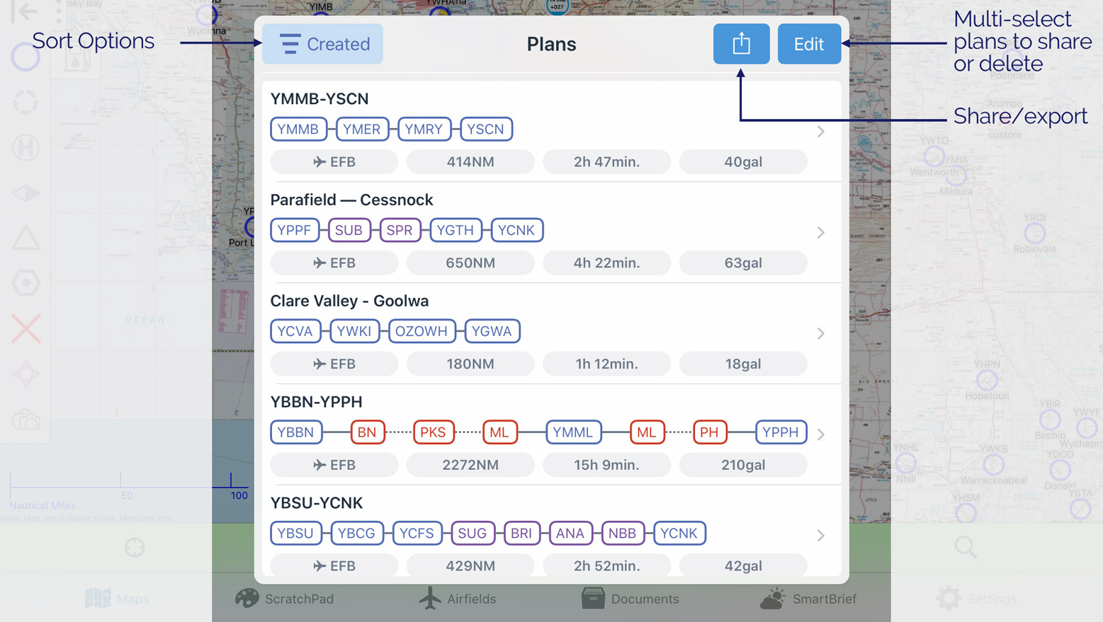
Image 8.4 Plans List
A typical Plans List is shown in Image 8.4. Every time you create a plan it will automatically be stored in the Plans List and will stay there until you delete it. To delete a plan (or multiple plans), tap the ‘Edit’ button, select the plans you would like to delete, then press the red delete button. You can also ‘swipe delete’ individual plans. To ‘swipe delete’ you hold your finger on the right of the plan you wish to delete and swipe (move your finger while contacting the screen) to the left. A red ‘Delete’ (rubbish bin) icon will appear for that plan. Tap it to delete.
The Plans List can be sorted using control in the top left corner. The sort options are as follows:
- Plan Name
Sort plans alphabetically.
- Distance
Sort by total distance of the plan.
- Departure
Sort by ETD set in the plan.
- Created
Sort by date of creation.
- Closest
Sort by distance from your location to the plan departure location.
Tap the sort button to select a sort option to sort in descending order. To sort in ascending order select the same option a second time.
Tap on a plan to activate it and enter the Plan Details view.
8.6. Map Planning
To create a flight plan on the map page, first tap near the waypoint that you would like to set as the origin of the plan. After tapping on the map the Closest Points popup will appear (Image 8.5). From here you can either use the ‘Add to Plan’ or ‘Direct To’ shortcut buttons, or, tap on the appropriate waypoint and select ‘Set xxx as Origin of Plan’
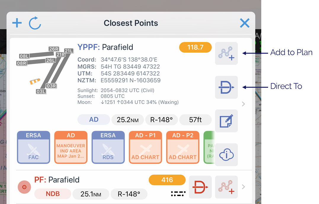
Image 8.5 Planning shortcuts on the Closest Points popup
You can continue adding waypoints to the plan using the method described above.
You can also insert waypoints into the middle of a plan as described below using the rubber band method; image shown below in Image 8.6:
Identify the segment where you wish to insert a waypoint
Tap and hold the magenta track line until it turns yellow, and a pink ring appears
While keeping your finger on the screen, drag your finger to where you want to go.
The Closest Points popup will appear, listing nearby waypoints
Tap on the waypoint you wish to insert, or tap the ‘+’ in the top left corner to create and insert a new User Waypoint
The plan will redisplay with the new waypoint inserted
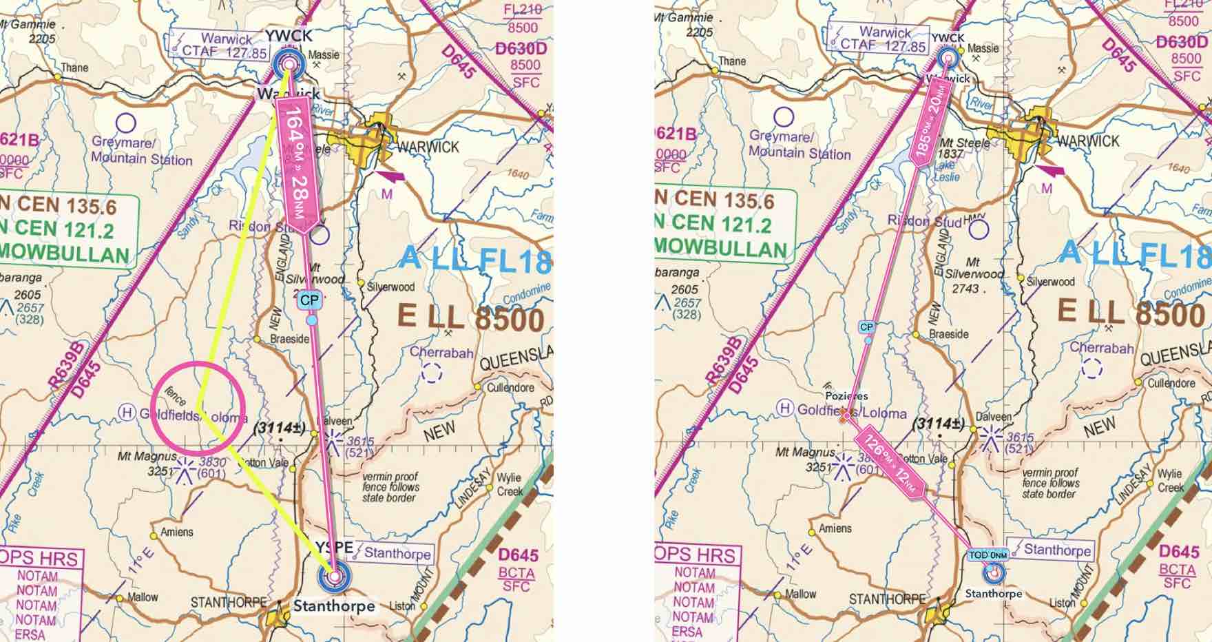
Image 8.6 Rubber band method
8.7. Plan Sheet
The Plan Sheet, or navigation log, is accessed from the map page by tapping the Plan Sheet button in the top left corner. There is also a Plan Sheet button on the Plan Details window. The Plan Sheet is shown below in Image 8.7.
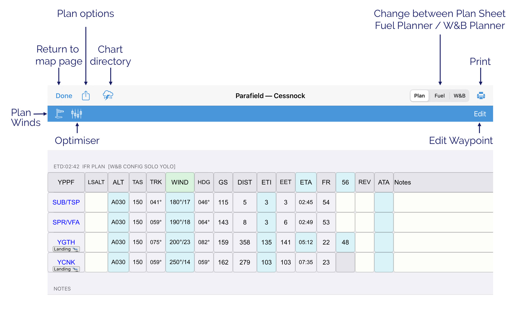
Image 8.7 Plan Sheet
There is a set of buttons across the top. Waypoints are listed sequentially down the left of the page. Light blue fields are editable, as are the pale yellow/straw coloured fields. Additionally, there are two special boxes in the top ‘origin row’. If you tap on the ‘ETA’ box you can set the departure time. If you tap what is the Fuel Log box in the top row you can set the fuel you will have on Startup (Ramp Fuel) from the origin.
From left to right the buttons at the top of the Plan Sheet are:
Done – go back to the map view
Plan options – opens a menu that allows you to set values for the overall plan such as the name of the plan, aircraft, pilot and departure time
Charts viewer - the Charts viewer is covered in more detail on the SmartBrief / Brief Page
Plan/Fuel/W&B – use this control to switch between the planner page (Plan), the fuel planner (Fuel) or the Weight and Balance planner (W&B)
Print – reveals options to print the plan sheet, fuel plan, or W&B
Windsock - described below in ‘Plan Winds’
Optimiser – tap this to get an Optimiser which automatically calculates groundspeed, ETI, and Fuel Burn for each leg at different altitudes
Edit – tap this to allow the insertion and deletion of waypoints in the plan.
You can scroll the planner horizontally as well as vertically. This is how the planner works on the iPhone. To aid entry in large plans, a ‘fill down’ option is available in the LSALT, ALT and WIND columns. Simply tap on an entry in these columns, enter the value, then tap the fill down arrow (initially it will be greyed out), then tap enter. Rows including the one you tapped and all those below will be filled in with the value you entered (Image 8.8).
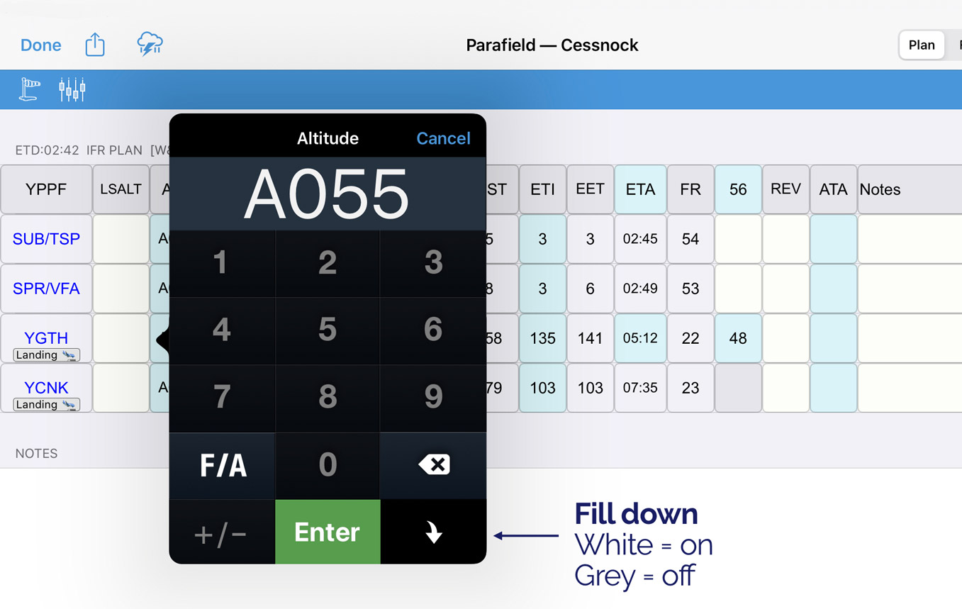
Image 8.8 ‘Fill down’ button
A ‘Notes’ column is available on the right hand side of each segment, and there is also a large block section at the bottom of the Planner that can be used for notes.
The columns in the Plan Sheet are described below.
Waypoints
The waypoints listed in the left hand column in blue capitalised text are as per the plan. You can edit these legs by tapping the ‘Edit’ button in the top bar, which will reveal ‘+’ and ‘-’symbols. See Edit Mode for further details. Tapping on a waypoint will designate that waypoint as a landing and optional refuel point. The popup in Image 8.9 will result.
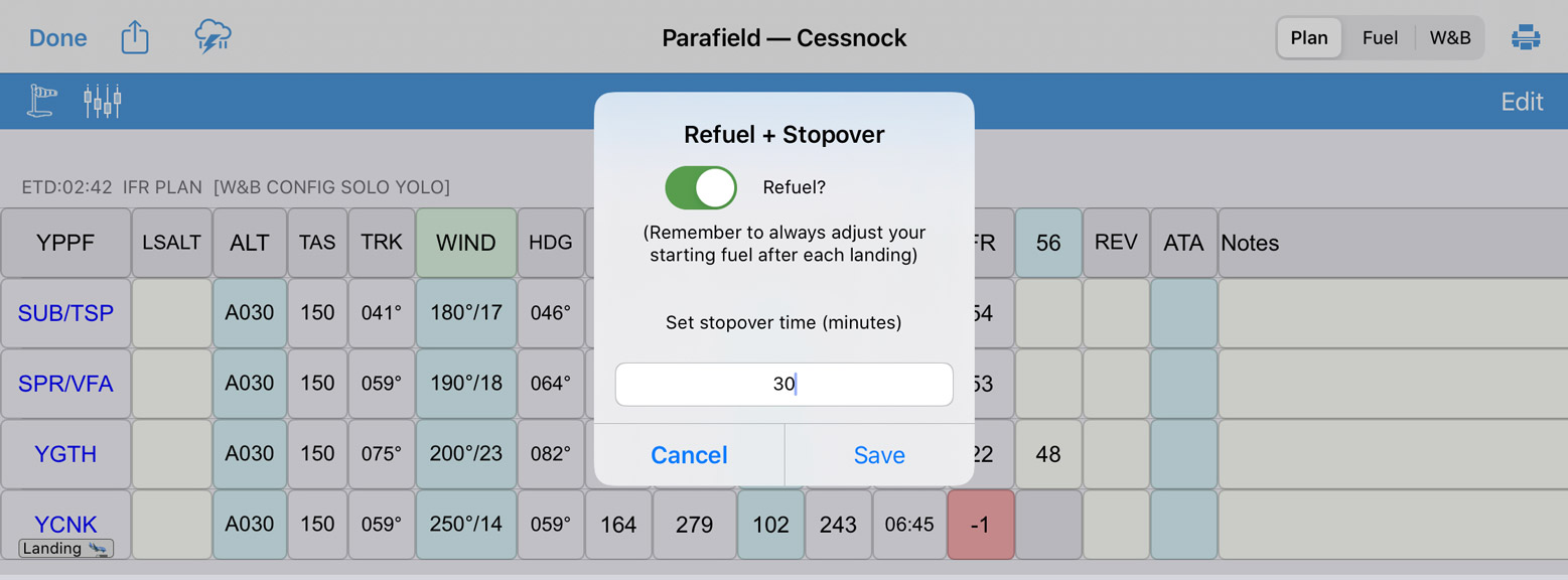
Image 8.9 Setting & landing/refuel point
Use the toggle to choose between refuelling and not refuelling (green toggle = refuelling, grey toggle = not refuelling). You can also enter your expected stopover time in minutes. This time will be taken into account for calculating ETAs, and when pre-filling the NAIPS or IFIS flight plan submission form.
If you have designated the landing point as a refuel stop then a blue cell appears in the waypoint row, next to the Fuel Remaining (FR) column. The fuel amount in this cell comes from the ‘Default Start/Refuel Amount’ (or ‘Fuel Capacity’ if default amount is not set) as per the aircraft profile. You can change this amount by tapping on the blue cell.
Note
If you are not refuelling, you should adjust the fuel in the Fuel Log column after every landing.
All landing points will be indicated on the Plan Sheet with a ‘Landing’ label underneath the waypoint name. The final waypoint in your plan will be assumed to be a landing point and will automatically display the landing label.
Alternates
Tapping on the very last waypoint in the plan turns that waypoint into an alternate. The alternate label will appear underneath the waypoint name, and the landing label will move to the destination above, as shown in Image 8.10
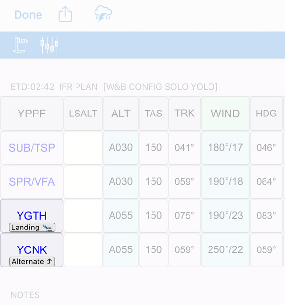
Image 8.10 Setting and alternate
The app will treat the alternate calculations as a new climb/cruise segment, starting at aerodrome elevation of the previous leg. The alternate will be added to the NAIPS flight notification ‘Alternate’ field. The alternate fuel will be shown in the fuel tab. Alternate fuel comprises of a climb from the previous waypoint altitude to the specified cruise altitude, cruise from TOC to overhead the destination plus variable for the route total.
LSALT (Lowest Safe Altitude)
Note
There is an LSALT Assistant feature in OzRunways that can help you calculate your LSALTs. See Terrain and Airspace for more information.
When planning by a recommended IFR route where an LSALT is available for a segment in the Airservices Australia dataset used by OzRunways, it will be automatically shown in the LSALT column. If there is no LSALT present, the user can enter the desired LSALT. The displayed LSALT can be overtyped by the user at any time by tapping on the cell.
Altitude
Altitude is entered in the FL format. For example, 5500 ft is entered as A055. Tapping on the bottom right ‘fill down’ tile in the number pad allows the altitude to be set for all legs, as shown in Image 8.8. A descent point is displayed for the last leg on the map, using the descent rate/TAS provided in the aircraft profile.
TAS (True Airspeed)
Cruise TAS is displayed as per the aircraft profile. This is for display purposes and does not include climb TAS, however climb TAS is used in the time/fuel calculations.
TRK (Track)
Track is displayed in degrees Magnetic (ºM) for the appropriate leg.
Wind
Winds are entered & displayed in degrees True (ºT). OzRunways converts to degrees Magnetic (ºM) for all calculations. Wind can be set for legs individually, or all legs using either the ‘fill down’ button from a leg entry, or the auto-fill winds. Auto-filling winds is described below in the Plan Winds section.
HDG (Heading)
HDG required to ‘make good’ planned track. Shown in degrees Magnetic (ºM).
GS (Groundspeed)
The groundspeed which has been calculated for a leg, including wind. For a leg which involves a climb, the GS shown is the average GS for that leg. Groundspeed is calculated at cruise altitude until destination.
Distance
Distance of the leg, in NM.
ETI (Estimated Time Interval)
Estimated Time Interval of the leg (i.e. the length of time the leg will take to fly). Display is in minutes. Where Airwork is desired at a waypoint, the waypoint ETI button (blue background) can be pressed to add a delay (DLA) in minutes. The entry can reflect either Airwork (AWK) or Hover (HVR), however the AWK/Hover toggle will only appear when the Hover Burn is present in the aircraft profile being used. Once a number of minutes is entered, press the AWK/HVR toggle to switch between the type of entry. The delays entered will use the appropriate fuel burns form the aircraft profile (AWK/Holding Burn and Hover burn respectively) however the DLA entered into the Flight Notification will be the cumulative amount of both delays. This ensures that for rotary wing operations, where fuel burn in the hold can vary markedly from the hover, that the calculation is accurate. No variable is calculated for AWK/HVR fuels. Once a AWK and/or HVR delay is entered, it will be shown as orange number(s) underneath the ETI. The delays will be added to the EET and ETA columns as well. For fixed wing aircraft, the hover fuel burn entry in the planner can be repurposed where a different burn rate is required during airwork.
EET (Estimated Elapsed Time)
The elapsed time of the plan to that waypoint in minutes. This field will be reset for waypoints after each landing point (i.e. it restarts at zero for a landing/refuel leg).
ETA (Estimated Time of Arrival)
Tapping on the blue word ‘ETA’ brings up some sliders you can use to set the plan Estimated Departure Time (ETD).
Where a waypoint is listed as a landing/refuel waypoint, the allocated stopover time in minutes will be added to the ETA at the point, with the resulting time serving as the subsequent Estimated Departure time. For example, if the ETA for an intermediate landing point is time 0135, and a stopover time of 30 minutes was set, then the planner will automatically set the departure time as 0205 for the next leg. If the ETI for the next leg is 20, the ETA for that next waypoint will be 0225 (0135 + 30min delay on the ground + 20 minute ETI to next waypoint).
FR (Fuel Remaining)
The Fuel Remaining Column displays the calculated fuel remaining based on the fuel burnt on a leg. The first leg will show a FR reflecting the subtraction of Taxi fuel. The fuel burn on a leg includes climb and cruise fuel (‘flight fuel’) plus the variable which has been set in the aircraft profile; any AWK and/or HVR fuel burn for that leg.
For example, on a leg which is the first leg of a plan: Start fuel 217L. Taxi fuel is 5L. Climb fuel is 10L. Cruise fuel of 15L. AWK of 30 minutes at 20L/hr. Variable 10%. Start Fuel – Taxi – Flight Fuel plus variable – AWK – HVR = Fuel Remaining, i.e.
217 – 5 – [(10+15)*1.10] – [0.5*20] ; 217 – 5 – 27.5 – 10 = 174.5
FR = 174.5, however only 174 will be displayed. The decimal value is still carried by the cell and applied to subsequent legs. This means even though the decimal is not visible, it is still being used for subsequent leg calculations.
Updating the wind during a flight will update the plan from that leg onward, including FR.
For the Alternate leg, the Fuel Remaining reflects a climb and cruise from the planned destination to the nominated cruise height. This leg is calculated using the normal cruise methodology, just as a first leg of a plan would.
See the Fuel Planner and `Alternates`_ sections for more detail on the fuel plan as well as how to add allowance for holding and approach fuels.
Fuel Log
The first field of the fuel log is the start fuel field (blue background). This is the ramp fuel. The ramp fuel is used in the calculation of the W&B, therefore it is important to ensure it is correct for the planning and the W&B, if it is used. Tap on this field to edit. The subsequent fuel log fields can be tapped on to enter fuel remaining at those waypoints for logging purposes. (Note that if the plan is edited, these entries may be lost.) Entries are stored even after a plan is exited, and must be cleared manually if you wish to use a plan again. The landing point does not have an editable fuel log field.
REV (Revised ETA)
Where desired, the pilot may enter a revised estimated time of arrival into this column. Note that if the plan is edited, the entries may be lost. Entries are stored even after a plan is exited, and must be cleared manually if you wish to use a plan again.
ATA (Actual Time Of Arrival)
This column is used to log the time of arrival at a waypoint. The time will be logged automatically when overflying the waypoint. This value can be overtyped, or a value manually entered if desired by the pilot.
Notes
This section may be used to add notes to a leg as required.
Plan Winds
To access the auto-fill wind, press the windsock button. Two options are presented as described below:
- GPWT Forecasts Low-level (Australia only)
Selecting this option will use data from the Grid Point Wind & Temperature charts. The data is interpolated for both altitude and time. This data is valid from SFC - 14,000ft, and only in Australia. For operations outside these conditions, use the NAIPS Wind/Temp option or fill the winds in manually.
- NAIPS Wind/Temp
Selecting this option will fetch the NAIPS Wind & Temperature profile, exactly as you would get if you were logged in to NAIPS on the Airservices Australia website.
- GFS (NZ only)
Available for New Zealand users, select this option to import Global Forecast System model winds into your navigation log. This is generally more reliable for NZ (especially below 5000ft) than the NAIPS Wind/Temp option.
Optimiser
The Optimiser calculates the optimum Altitude or Flight Level to fly for each leg of your plan, given the forecast winds. The app calculates Groundspeed, ETI, and Fuel Burn for every 2000 feet. Upon entering the optimiser, the app will automatically select the optimum altitudes (based on time) for each leg based on the available results. Although the optimiser can calculate the results on any leg based on the wind profile, the pilot needs to analyse the information to ensure the results meet their needs; the app does not know whether an altitude change between legs is sensible or not. Tapping on an altitude for a leg in the optimiser will cause the subsequent optimiser values to recalculate based on your selection. If LSALTs are included, these are also taken into account (Altitudes below LSALT are greyed out - not selectable). To use the Optimizer first press the windsock button and obtain the winds. Then open the Optimiser by selecting the slider button on the Plan Sheet. Once selections are complete, tap the route name in the top left corner to return to the plan sheet. Image 8.11 shows the result of examining the detail of a run of the optimiser. The arrows at the top right are for progressing from one segment to the next (i.e. takeoff to landing). Within a page, each leg will be shown (i.e. waypoints between takeoff to landing).
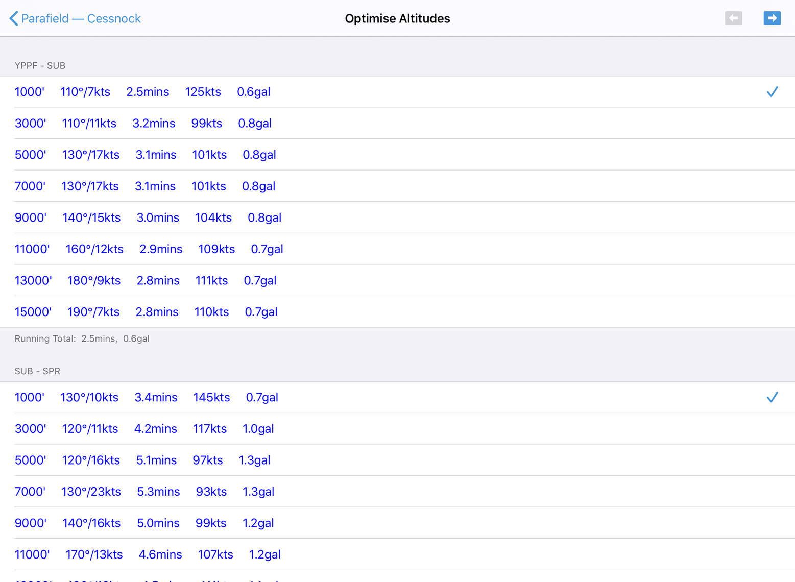
Image 8.11 Plan optimiser
Edit Mode
By tapping the ‘Edit’ button on the Plan Sheet you enter Edit mode as shown in Image 8.12
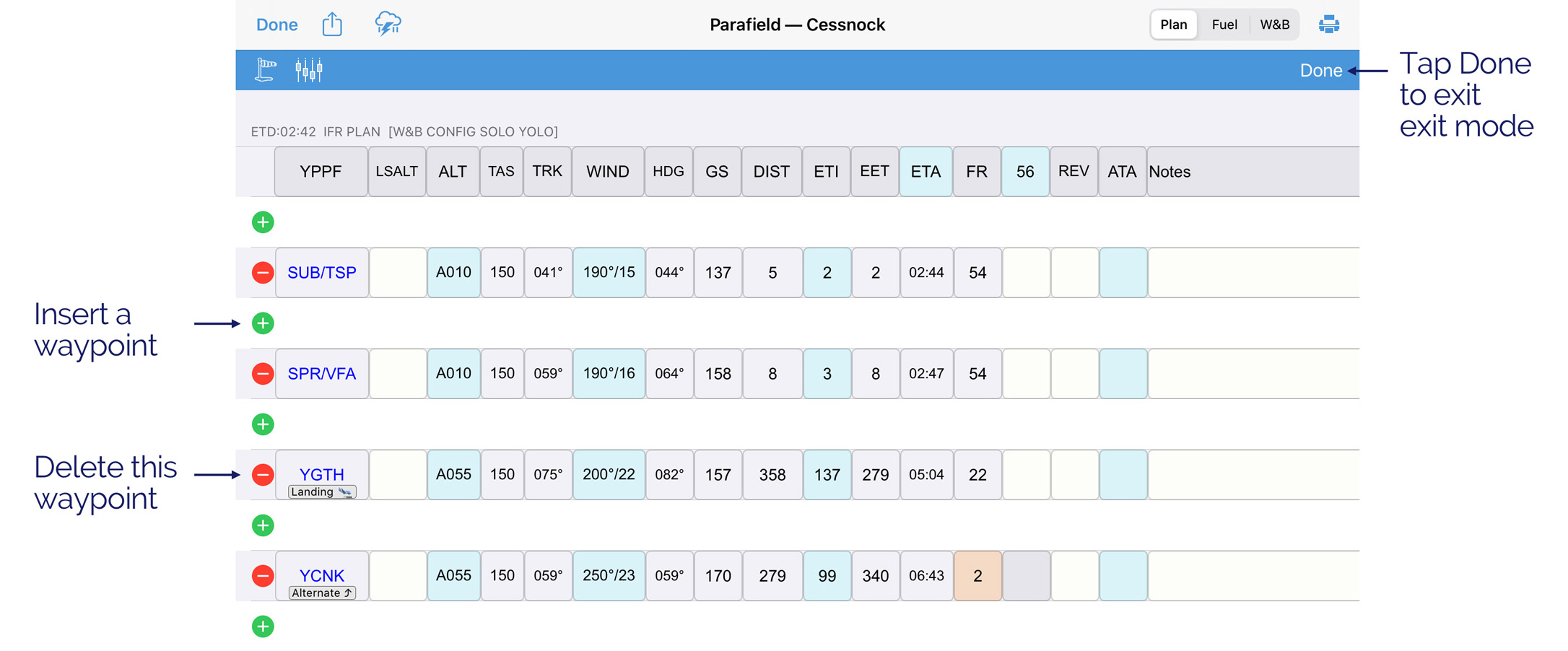
Image 8.12 Editing the Plan Sheet
Additional rows are added between existing waypoints with green plus signs in them. Red minus signs appear to the left of each existing waypoints. Tapping the plus sign will allow you to insert a waypoint between the waypoint above and the waypoint below. Tapping the minus sign deletes the associated waypoint. Tap the ‘+’ and a popup appears allowing you to search for a waypoint. You can either type in the desired waypoint in the search box, or tap one of the waypoint types to get a list of waypoints, waypoints closest to the centre of the segment in question will be displayed. This way, you simply define origin and destination and use this function to recursively select intermediate ADs/ALAs until you have all the waypoints you desire.
8.8. Plan Sheet (NEW)
Warning
The new plan sheet is currently under development and is only available to trial by request. We recommend verifying all critical calculations to ensure accuracy. If you encounter any discrepancies, please report them using the Help button located directly on the new plan sheet, or via the following link: https://airtable.com/appUSoOiglNKtZ1Jy/page3fzU2ev6nc1nv/form
The new plan sheet introduces the ability to add enroute alternates, destination alternates and multi-sector flight planning. The new plan sheet can be enabled in Settings → Preferences → Use new plan sheet.
The new plan sheet is accessed the same way as the previous plan sheet: from the map page by tapping the Plan Sheet button on the Bottom Right Bar. There is also a Plan Sheet button on the Plan Details window.
As shown in Image 8.13 the layout of the new plan sheet is similar to the old one. Waypoints are listed sequentially down the left of the page. Cells with small grey triangles in the top right corner are user editable. When you manually edit a cell the grey triangle will turn blue to provide a quick visual indication that you have manually entered or amended the data in the cell. The planner can be scrolled horizontally as well as vertically for use on smaller devices like iPhones.
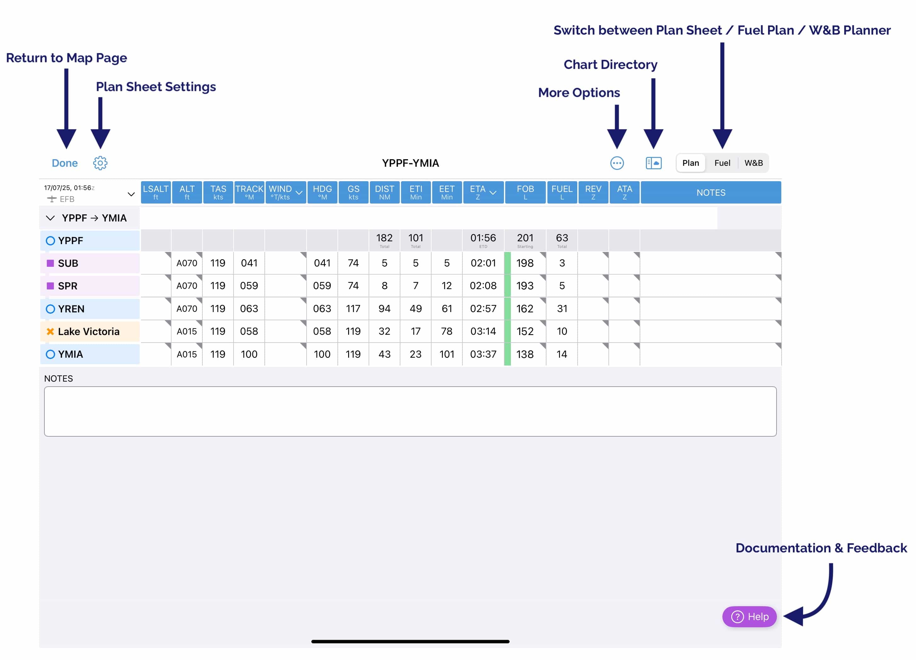
Image 8.13 New plan sheet
From left to right the buttons at the top of the Plan Sheet are:
Done – go back to the map view
Plan Sheet Settings – Set preferences such as displaying trip features (top of climb, top of descent etc.), and air route designators on the Plan Sheet. You can also show/hide and rearrange the ordering of columns.
More Options – The More Options button contains options for the currently active plan. If you have an appropriate subscription avionics export options for Avidyne and Dynon will appear in this menu. Additionally you can share the plan, generate a PDF Pack for the flight, print the Plan Sheet, submit to NAIPS/IFIS, or export the plan in various formats.
Charts Directory – Access various weather charts and briefings
Plan/Fuel/W&B – use this control to switch between the planner page Plan, the fuel planner Fuel or the Weight and Balance planner W&B
Help - The Help button opens this documentation and provides access to a ‘Feedback’ button. As this feature is still in development we appreciate any feedback as this helps us improve the Plan Sheet and ensure it meets your needs!
Departure time (ETD) and other flight details
To set your Departure time tap the white cell in the top left corner. This will open a popup as shown in Image 8.14.
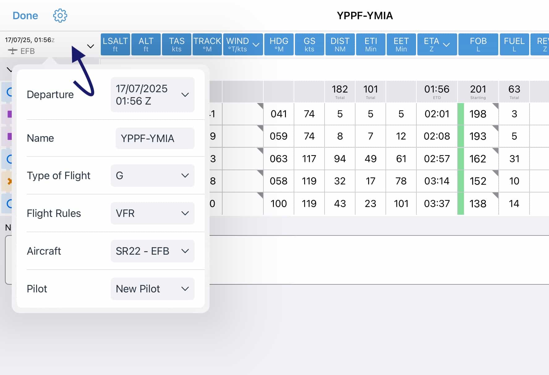
Image 8.14 Flight details popup
Departure - Opens a Scroll wheel to set your departure date and time. Tap Clear to remove the departure time entirely. Tap UTC to switch from UTC to your device’s local time zone. ‘UTC’ will be replaced by the abbreviated time zone, tap again to switch back to UTC. Tap Now to set the time to the current time.
Name - The name of the plan. Tap to rename if desired.
Type of Flight - Set the flight type/category. This will pre-fill into the NAIPS/IFIS form if you are submitting a Flight Notification.
Flight Rules - Set your flight rules (VFR or IFR). This will pre-fill into the NAIPS/IFIS form if you are submitting a Flight Notification.
Aircraft - Select the aircraft profile associated with this flight plan. Performance calculations will be based on the selected aircraft profile. For more information about aircraft profiles see Aircraft
Pilot - Select the pilto profile associated with this flight plan. Pilot profiles are created on the Settings Page. The name and phone number from the pilot profile will be pre-filled into the NAIPS/IFIS form if you are submitting a Flight Notification.
Adding or changing fuel amount
To set or change your start fuel amount tap the starting cell in the FOB column. If you have set a ‘Fuel Capacity’ and/or ‘Default Refuel Amount’ in your Aircraft Profile, these will be offered as options.
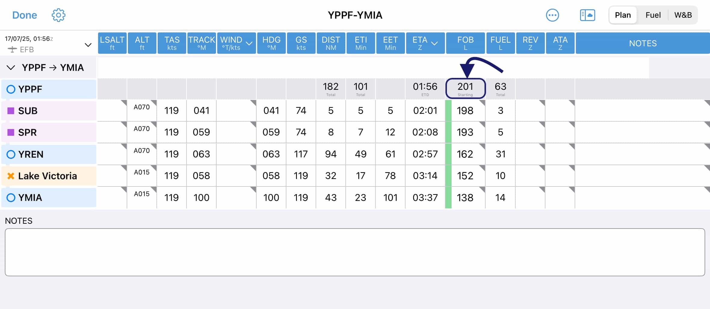
In-flight revised fuel estimates can be made by tapping the relevant cell in the FOB column. Here your planned Fuel on Board (FOB) will show. Use the keyboard to enter a revised fuel value, or, tap the [+] or [-] buttons to increase/decrease by 1 unit. Tapping Clear will reset the FOB for this leg back to the planned value. When you enter a value that is different to the planned value, the small grey triangle in the corner of the cell will turn blue to indicate pilot input. This is true of most editable cells on the plan sheet.
Waypoints
Waypoints on the plan sheet share the same symbol & colour conventions as on the map page. Tap on a waypoint to open the waypoint menu. Image 8.15 shows the result of a tap on YREN, with the following options:
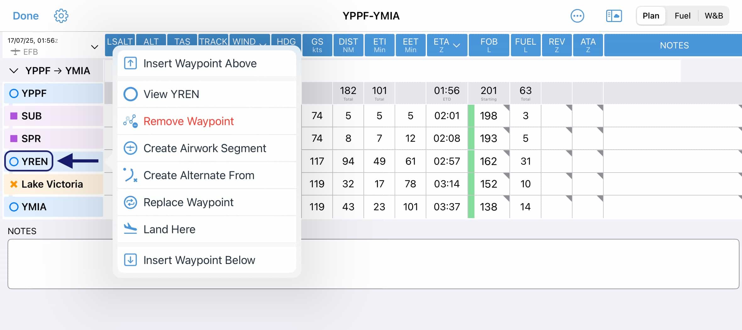
Image 8.15 Waypoint menu
Insert Waypoint Above – opens a Quick Planner dialog allowing you to insert one or more waypoints or air routes above the selected waypoint
Insert Sector Before (Only shown when you tap on the very first waypoint in a given sector) Opens the Quick Planner where you can enter a new sector, including intermediate waypoints if desired
View <waypoint> – opens the waypoint details view with various information about the waypoint
Remove Waypoint - removes/deletes the waypoint from your plan
Create Airwork Segment - tap add airwork at this location. A popup will prompt you to enter your estimated air work time, after which a new row is created with this number of minutes in the ‘ETI’ column. To remove airwork, tap on name/label of the indented airwork row and choose ‘Cancel Airwork’
Create Alternate From - tap to create an alternate for this waypoint. You can specify both a waypoint and a route. You can have as many alternates as there are waypoints in your plan! (note: one alternate per waypoint)
Replace Waypoint - opens a Search dialog allowing you to search for any waypoint to replace the selected waypoint
Land Here - Add this waypoint as a landing point. This will split your plan into two ‘sectors’, both of which are still visible on a single plan sheet
Insert Waypoint Below – opens a Quick Planner dialog allowing you to insert one or more waypoints or air routes below the selected waypoint
Insert Sector After (Only shown when you tap on the very last waypoint in a given sector) Opens the Quick Planner where you can enter a new sector, including intermediate waypoints if desired
Remove Landing (Only shown for the very last waypoint on a multi sector plan) Remove this landing point and cancel the sector, all the associated waypoints will remain in the plan
LSALT (Lowest Safe Altitude)
Note
There is an LSALT Assistant feature in OzRunways that can help you calculate your LSALTs. See Terrain and Airspace for more information.
When planning via IFR routes that have a published LSALT, the LSALT will be automatically populated in this column. You can tap any LSALT cell to enter or overwrite the value.
Wind
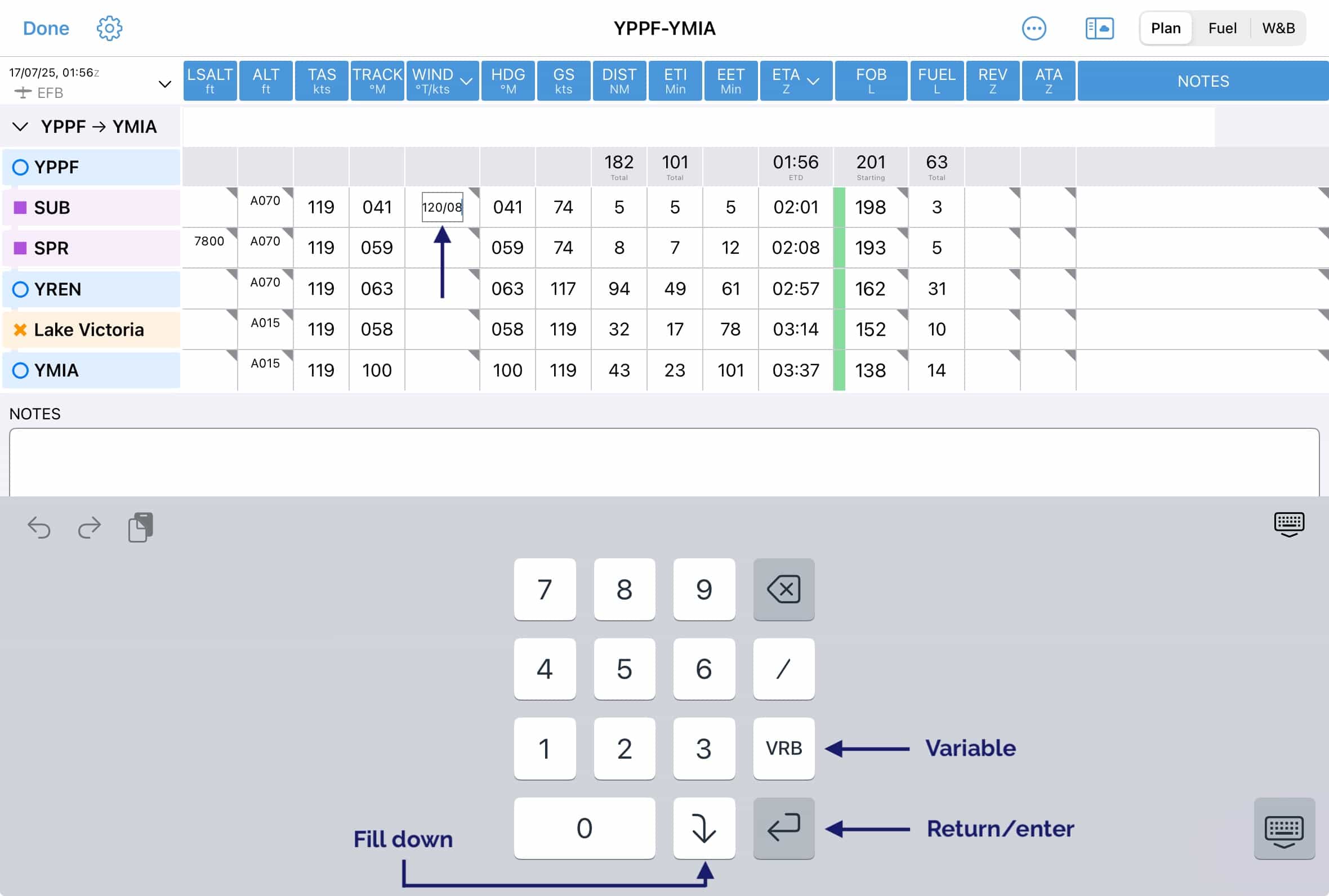
Winds can be entered manually by tapping on any wind cell in the applicable waypoint row. Winds are entered & displayed in degrees True (°T). OzRunways converts to degrees Magnetic (°M) for all calculations. You must enter the wind including the / e.g. for wind at 145°, 17kt you would enter 145/17.
Variable wind can be entered by tapping VRB, followed by /, and then enter the speed e.g. VRB/02
Press return/enter to save your entered wind for this cell only, or press the ‘fill down’ arrow to save for this cell and all following wind cells.
Winds entered manually (indicated by a blue triangle in the corner of the applicable wind cell) will not be overwritten by winds that are fetched automatically, as described below.
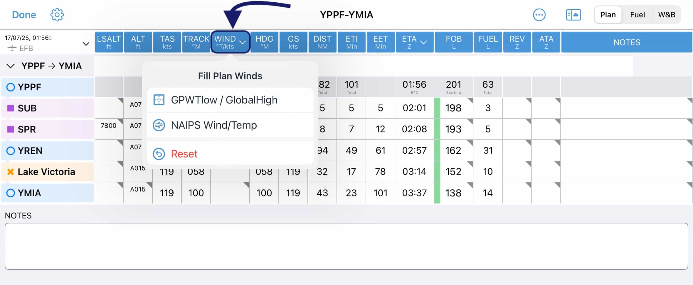
Image 8.16 Fetch winds
Winds can be fetched automatically by tapping the WIND heading cell as per Image 8.16. There are various wind sources:
- GPWTlow / GlobalHigh (Australia only)
Selecting this option will use the digital Grid Point Wind & Temperature data, interpolated for altitude and time, from SFC - 14,000ft. Above 14,000ft the Global Forecast System winds are used.
- NAIPS Wind/Temp
Selecting this option will fetch the NAIPS Wind & Temperature profile, exactly as you would get if you were logged in to NAIPS on the Airservices Australia website.
- GFS (New Zealand only)
Selecting this option will use the Global Forecast System model winds.
Winds fetched automatically will not overwrite any manually entered winds.
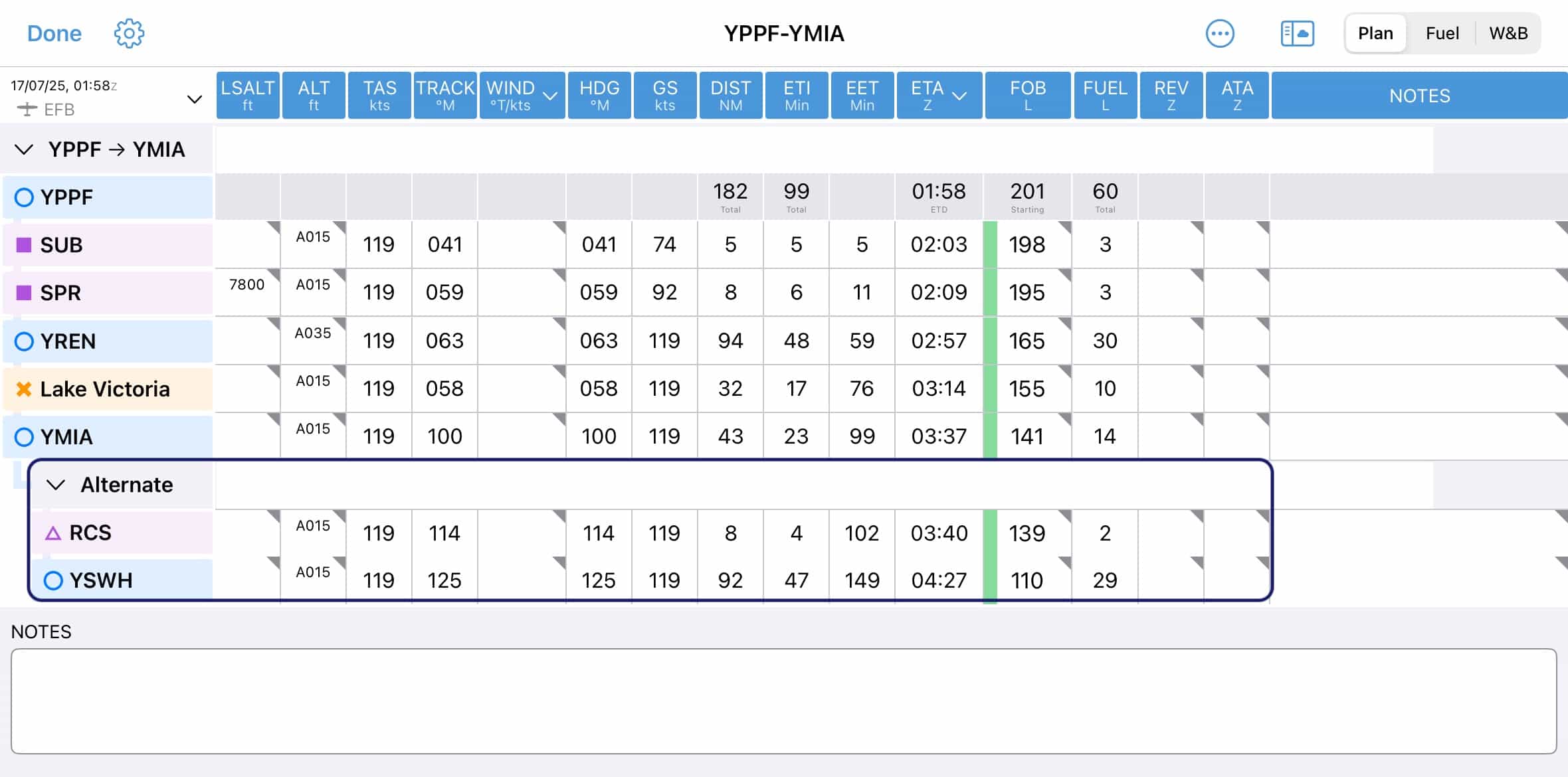
Alternates
To add an alternate to your plan, tap on the applicable waypoint and select Create Alternate From. This will open a Quick Plan dialog where you can enter your alternate waypoint, and if desired, a route to that waypoint. If this is an IFR plan air routes will be suggested as per usual in the Quick Planner. Tap the caron (⋎) on the ‘Alternate’ row to collapse the alternate leg (condense to a single row), keeping it out of the way while you don’t need it. Tap the caret (>) to expand. To remove the alternate tap the ‘Alternate’ cell (away from the caret/caron) and then tap Cancel Alternate.
You can have multiple alternates in a plan, with a limit of one alternate per waypoint.
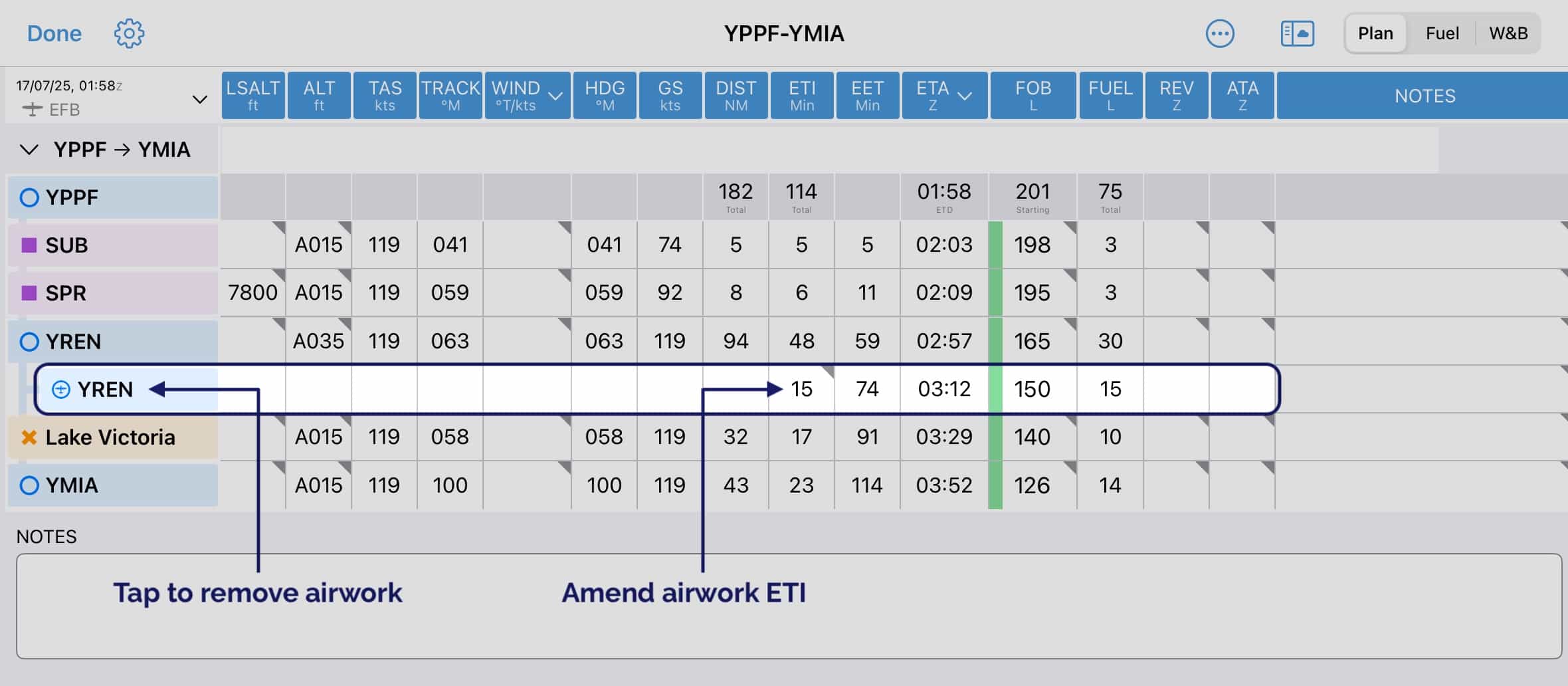
Airwork
To add Airwork to a plan tap on the applicable waypoint, then tap Create Airwork Segment. Enter your estimated airwork time in minutes and tap Create Airwork. This will add a new airwork row to the plan sheet, underneath the associated waypoint. To change the duration of the airwork tap the ETI cell in the airwork row. To remove airwork, tap the waypoint label on the airwork row, then tap Cancel Airwork.
Multiple Sectors
The new Plan Sheet supports multiple sectors. A sector is defined as take-off to landing. There are two ways to create a sector:
If you make an intermediate point a landing point, the plan will automatically split into two sectors. e.g. in Image 8.17 we have tapped on YREN and selected Land Here. We now have our first sector: YPPF → YREN, and a second sector YREN → YMIA
To create a new sector, tap on the very last waypoint in your plan and select Insert Sector After. This will open the Quick Planner where you can create your second sector. If the plan is set to IFR the Quick Planner will suggest air routes where available.
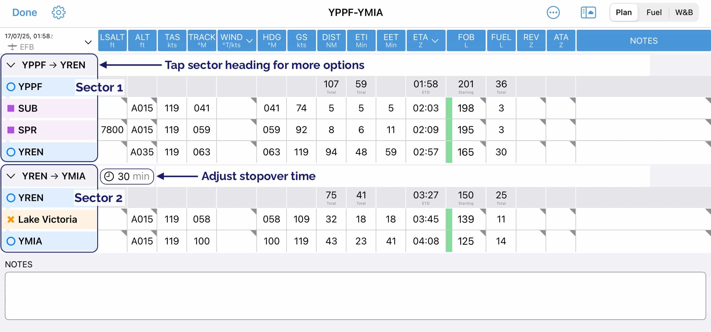
Image 8.17 Multi Sector Planning
Tapping the caron (⋎) on the sector heading row will collapse the sector and show only a summary of the waypoints. Tap the caret (>) to expand the sector again.
Tap on a sector heading to reveal more options as follows:
Remove Sector Deletes the whole sector, including any intermediate waypoints
Remove En Route Waypoints Deletes any and all waypoints between the the origin & destination waypoints, for this sector only
Cancel Landing (Only shown on the second and subsequent sectors) Remove this landing point and cancel the sector, all the associated waypoints will remain in the plan
8.9. Fuel Planner
The Fuel Planner is accessed by tapping the ‘Fuel’ button at the top right of the Page Planner. A typical view is shown in Image 8.18
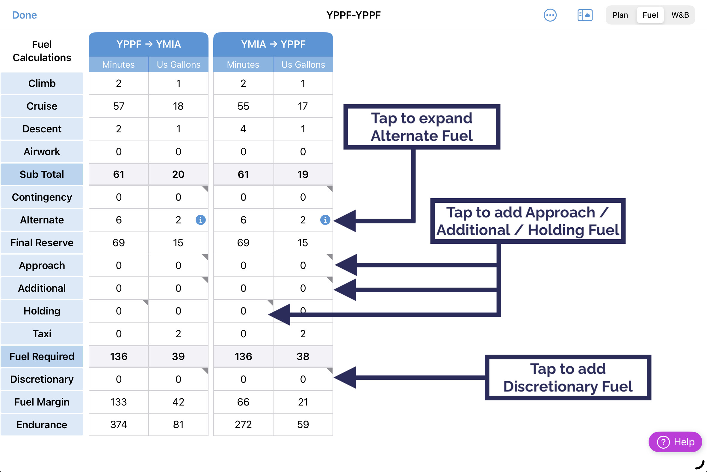
Image 8.18 Fuel Planner
On this flight we land at YMIA.
If the number of segments exceeds five, two arrows appear in the top menu that can be used to move between segments. The light blue entries in the table may be edited. The Fuel Margin will turn red if you are burning into your reserve fuel or if the segment uses more fuel than is loaded at the start of the segment. Below is a breakdown of each item of the Fuel Planner, and explains how it is calculated.
- From/To
Shows the origin and destination.
- Climb
Calculated as per the aircraft profile, for the cumulative climbs across the plan.
- Cruise
Calculated as per the burn rates specified in the aircraft profile.
- Hover
As per the Hover times set in the plan, at the rate specified in the aircraft profile.
- AWK (airwork)
As per the AWK times set in the plan, at the rate specified in the aircraft profile.
- Sub Total
Sub total of climb, cruise, hover, and AWK fuel.
- Contingency
Contigency fuel calculated as per the values specified in the aircraft profile, applied to the climb, cruise, airwork/hover, and approach total.
- Alternate
Reflects the climb and cruise from the planned destination to the alternate at the altitude nominated in the plan. This can be expanded to show the planned fuel burn by tapping the information icon Image 8.19.
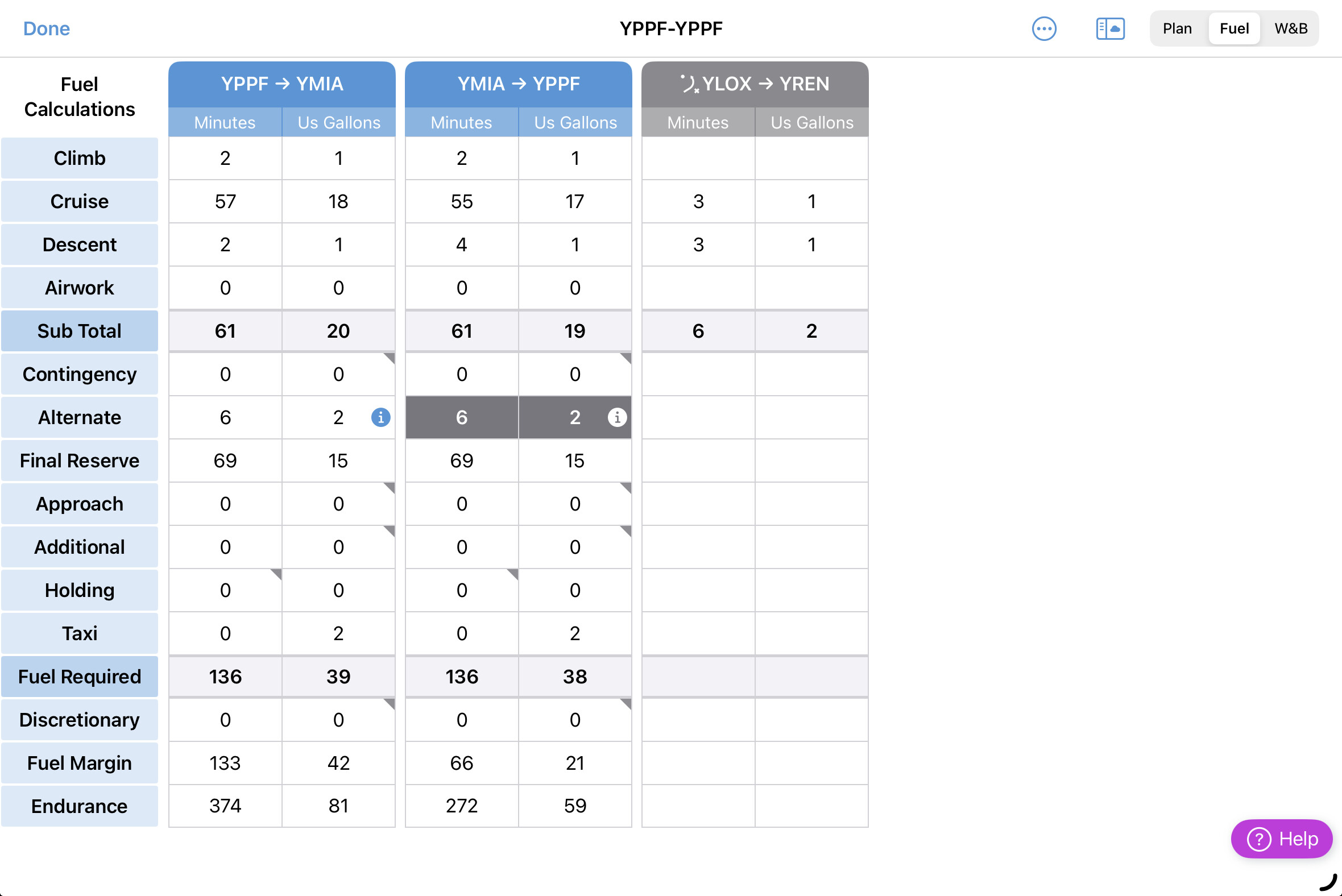
Image 8.19 Expanded Alternate Fuel Plan
- Final Reserve
As specified in the aircraft profile.
- Approach
Additional fuel for IFR approaches can be added. Time is automatically calculated according to AWK/Holding burn rate in aircraft profile.
- Additional
Additional fuel can be added here where required.
- Holding
User set, in minutes. Calculates at the AWK/Holding burn specified in the aircraft profile. For example, INTER/TEMPO holding.
- Taxi
The amount of taxi fuel as set in the aircraft profile.
- Fuel Required
Cumulative totals of all fields.
- Discretionary
A place to add (or remove) fuel not otherwise required by legislation, at the pilots discretion.
- Fuel Margin
Calculated by subtracting the Fuel Required figure from the Endurance fuel or the specified Margin Burn rate as set in the aircraft profile.
- Endurance
Cumulative totals of Fuel Required and Fuel Margin. This time is used in the Flight Notification. Calculated at the AWK/Holding Burn Rate or the Cruise Burn rate, as specified in the aircraft profile.
8.10. Weight and Balance Planner
The Weight and Balance Planner may be accessed by tapping the ‘W&B’ button at the top right of the screen. A typical view is shown in Image 8.20
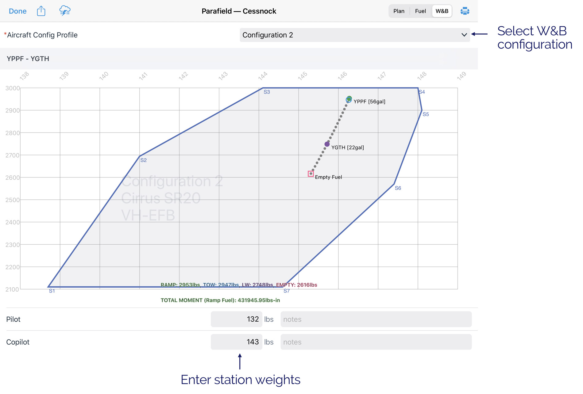
Image 8.20 Weight & Balance Planner
The weight and balance tab uses the active W&B profile (set up in aircraft profile). Users MUST ensure they are using a correct profile before relying on the W&B sheet. Multiple W&B configurations can be defined in a singular aircraft profile. Where this is the case, you can select which profile to use using the dropdown box at the top of the W&B sheet. Individual station weights can be changed by tapping on them. Fuel displays based on the plan sheet start fuel, planned landing fuel (as per last FR on plan sheet), and critically Zero Fuel CG. Ramp weight, TOW, Landing Weight, and Zero Fuel Weight are shown at the bottom of the graph colour coded to the plots on the graph. Total Moment for the ramp weight is also displayed. Where a plot appears outside the envelope it will be shown in RED. Each segment of the plan (segment = takeoff to landing) has its own Weight & Balance sheet which can be found by scrolling down the page. Where an alternate is specified, the W&B profile shows the alternate as the landing point.
Warning
The OzRunways W&B is simply a calculator that relies on accurate input of data - it has NO way of knowing if the data you enter is correct or not, compared to your aircraft. The system is not capable of warning you if inaccurate data is entered into the app. You must be proficient at W&B to use this system safely, and you must ensure the data you enter is correct.
8.11. Printing Plans
Tap the Printer icon to reveal some printing options as shown in Image 8.21
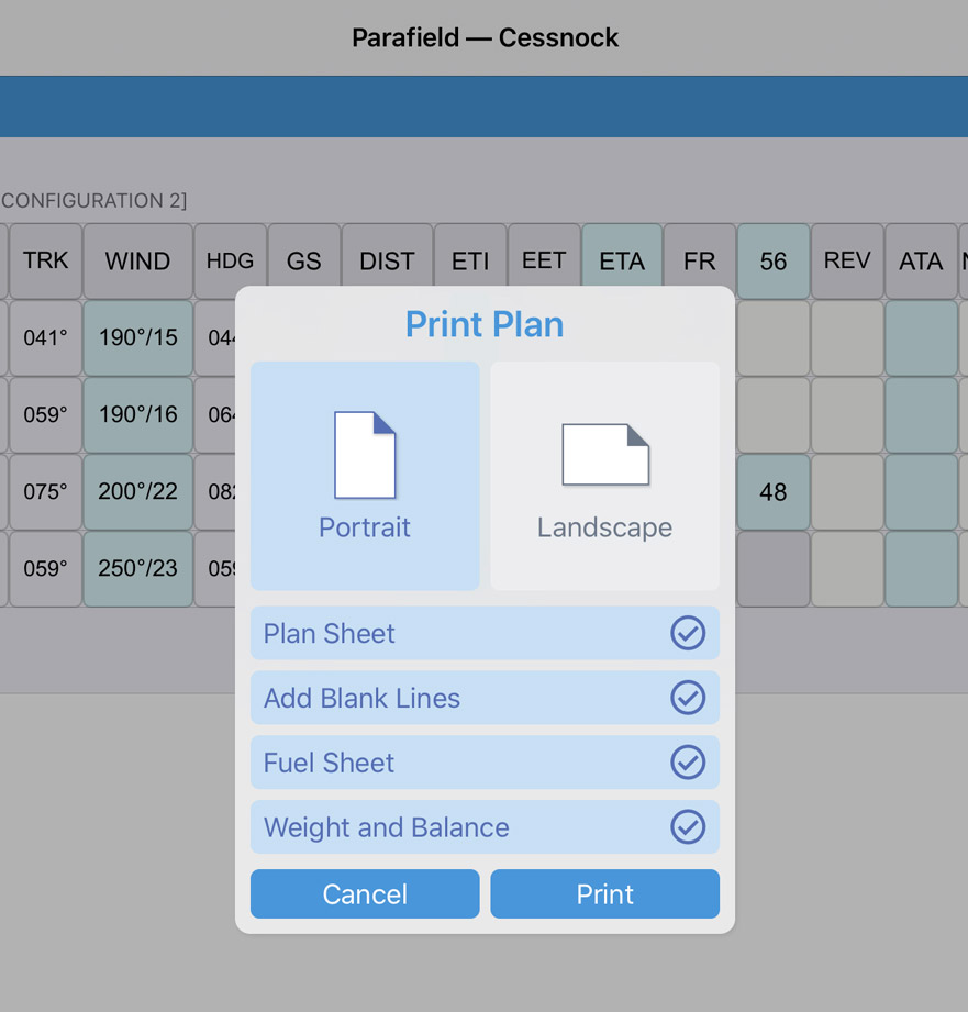
Image 8.21 Print Plan
You can choose between Portrait or Landscape orientation. Use the check boxes to select which items you want to print. Add Blank Lines will add a blank row beneath each waypoint on the plan sheet, handy if you want to jot down your own notes after printing.
Devices running iOS 10 and above can also export to PDF by tapping the Printer icon and then tapping the ‘Share’ button in the top right corner as shown in Image 8.22
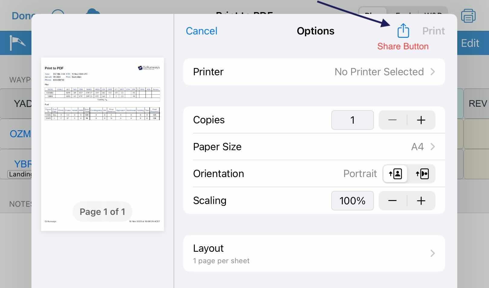
Image 8.22 Share Button
8.12. Exporting Plans
Tap the Help button at the top of the Map Page and select ‘Share Current Plan’
Alternatively, use the Share button on the Plan Details screen.